
AS THIS IS THE MOST IN DEMAND ENTRY. I’M CONSTANTLY UPDATING IT.
IF YOU HAVE ANY QUESTIONS PLEASE ASK.
UPDATES
• 2021.08.05 FINALLY the official source provides a way to do it.https://www.home-assistant.io/docs/energy/electricity-grid/
- 2021.02.16 New option in HA is not calculating usage with the Utility meter the same way as previously. (In any case this setup asides from a reboot of the setup once a year it’s been great. BUT there are surely better options than a now almost 3 year old system)
- 2020.08.09 was browsing AE and saw this Dual Display 40A 63A 230V Din Rail Adjustable digital Over Under Voltage Relay Surge Protector Limit Over Current Protection
- 2020.04.26: all is well with this setup. Just watched “Tech with Shae and his DIY home monitor setup. Good for the people of North America.https://youtu.be/x5r0qquFne8
- 2020.02.20: my first failure occurred. Roughy a month since I updated to a different nodemcu and updated Tasmota to 8.1. The readings have frozen for about 24hours. Logging into Tasmota is not possible, Tasmota seems frozen/unresponsive.
- 2020.01.26: After almost 2 years of continuous flawless operations I’ve decided to update the Tasmota firmware from 5.12 to 8.1. It didn’t go well (post coming soon). But it seems to run without issue. Link
- It seems the pzem-004 v3 has a different configuration in Tasmota to the previous versions https://github.com/arendst/Tasmota/wiki/PZEM004T-Energy-Monitor. Maybe the new settings are enough, maybe like some report it won’t work.
- 2019.09.11 (JST) The HookUp has a ShellyEM video as well https://www.youtube.com/watch?v=5RyDxZLA8b8
- 2109.08.19: Using a Shelly seems easy. https://youtu.be/pdo0IzpEEMI see links in video description too.
- 2019.07.14: hmm must have missed Dr ZZz talking about the PZEM ealier this year https://youtu.be/_djX-7c2kg4?t=3995
- 2019.06.03: This setup has been rock solid for over a year without any changes. 👌
- 2019.04.26: from Sendorm is a cleaner way to power the system without a separate usb power adapter
- 2019.04.16:To simplify the process of the code below I have put it online at https://github.com/halfforked/PowerMeter/tree/master
- 2018.09.09 – Post split in multiple pieces see part 2 as well
ALTERNATIVES* (added 2019.03.02)
- Using a Shelly seems to be an easier way to go. Posted above as well. https://youtu.be/pdo0IzpEEMI
https://www.youtube.com/watch?v=5RyDxZLA8b8 - This is an Energy meter (for a single device?) but the principle is the same. Note the if you try this you’ll NEED a SPLIT COIL instead. https://github.com/arendst/Sonoff-Tasmota/wiki/PZEM004T,-Wemos-D1-Mini-and-a-1602-I2C-display
- SMART METER: if you have a smart meter then things may get much easier for you. https://cloudenius.com/2018/08/04/use-smart-energy-meter-with-home-assistant/
- PRE-BUILT/service – 3 phase: https://efergy.com/engage-online-monitoring/ (unsure about integration in Home Assistant)
- PRE-BUILT/service: https://openenergymonitor.org/ (unsure about integration in Home Assistant)
- There is a suggestion for a 3 phase system on https://community.home-assistant.io/t/whole-house-power-monitoring-single-phase-for-under-30/68793/15
The standard disclaimer: Please do not attempt anything seen here if you’re not comfortable with breakers and mains power.
At this point I had BRUH room sensors in every room (except bathroom) and outside.
The next step was to have whole house monitoring. Which was finally done this morning.
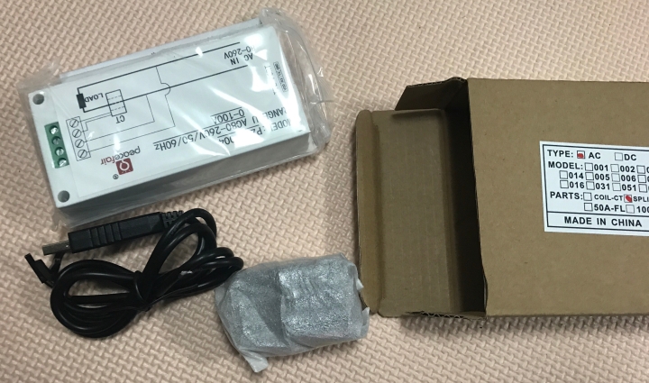
A couple weeks back I received my PZEM-004. Without a clue on how to hook it up to hassio. I figured there had to be a way.
I was ready to reflash a nodemcu with original programming if I had to. I wanted house wide power monitoring but couldn’t get many ready made products in Japan nor wanted to pay 200-500USD for them. For example this awesome looking SENSE unit reviewed a while back by BRUH.
Sure I won’t have the detection software that will figure out the various appliances for me, which would be very nice, but realistically at sub 30$ I’m quite happy.
The PZEM-004 with display, split coil current transformer (CT) with a usb wire for power set me back a tiny 2116JPY (20USD) [nodemcu was 3USD]
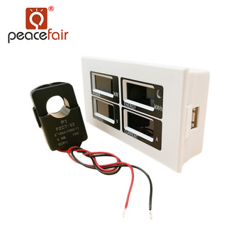
This is what I bought. PZEM-004 link here. I commented that it does make a buzzing noise when powered, if it’s an issue in tiny-house-Japan. Of course if you want an even cheaper one, get it without the display. (Although I don’t recommend it as with display it’s easier to test)
TESTING:
- Using a cable with a plug on one end and bare cable on the other (i.e. like a cut extension cord). I used a cable bare on both ends and temporarily attached a plug to one end.
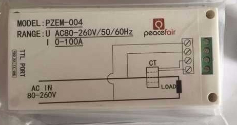
- Connect the bare cable ends into the PZEM-004 as per the instructions on the unit
- Connect the coil (if not already attached) and put ONE of the two wires in the extension cable through it again as per the instructions on the unit. (not both wires as the currents will cancel each other out)
- Power the PZEM004 via the included USB cable. I opted to use a double USB charger with one side powering the NodeMCU and the other powering the PZEM004 plugged into a power strip with a switch. (I’m guessing you could *maybe* power the PZEM004 from the VIN pin of the NodeMCU as this is the same as connecting to the USB plug directly)
UPDATE 2019.04.26 from Sendorm
One thing to add, I am powering the pzem-004t TTL from the nodemcu VU pin and it is working perfectly. It seems a separate usb power adapter is not necessary after all.
https://community.home-assistant.io/t/whole-house-power-monitoring-single-phase-for-under-30/68793/9
- USING a power strip with a switch at OFF, plug in the “plug” end of the cut extension cable.
- Clearing away any other debris, things around, turn on the power strip.
- You should be getting a reading on the PZEM004 (if you have a screen)
Providing power to the PZEM004 to TEST it worked without a hitch with a cable to the mains. I used a cable with a plug on the end and bare wires on the other. The bare wires powered the PZEM004 and splitting cable into the two wires carefully preserving the rubber the coil was attached to ONE of the wires. After the setup I plugged the cable into the wall and power readouts appeared on screen. TEST successful.
How to get it to play nicely with TASMOTA? (then Home Assistant)
- [update 2019.09.11] I use the nodeflasher, it’s old but just works well for me, and flash TASMOTA v6.6.0 onto a nodeMCU. There is no fussing around with Arduino or anything anymore
NodeFlasher
TASMOTA v6.6.0 this sonoff.bin (standard) - [original] Flash tasmota on the NodeMCU or Wemos. The Sonoff basic doesn’t have the pins necessary to connect with. (I flashed with the ARUDINO IDE as I wanted to select the WIFI AP mode and Enter a name for this NodeMCU as “powermeter“)
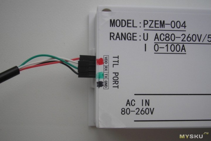
**If using the Arduino IDE be sure not to use ESP8266 version 2.4.X I would downgrade to 2.3.0 for now (2018.09.09) link - Make sure the PZEM-004 is disconnected or the switch is off. Using the picture on the back of the unit connect the PZEM RX -> NODEMCU TX and the PZEM TX-> NODEMCU RX pins.
That pretty much takes care of the physical connection.
- Connect to the tasmota firmware at the IP address on your network
- Set to generic
- Set the pins you chose (in my case see below)
- Enter the MQTT server info
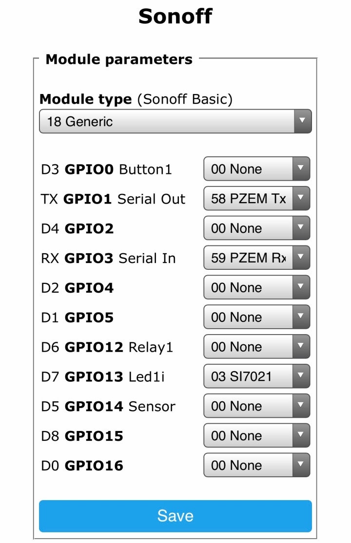
And that should be it for Tasmota-NodeMCU (Wemos).
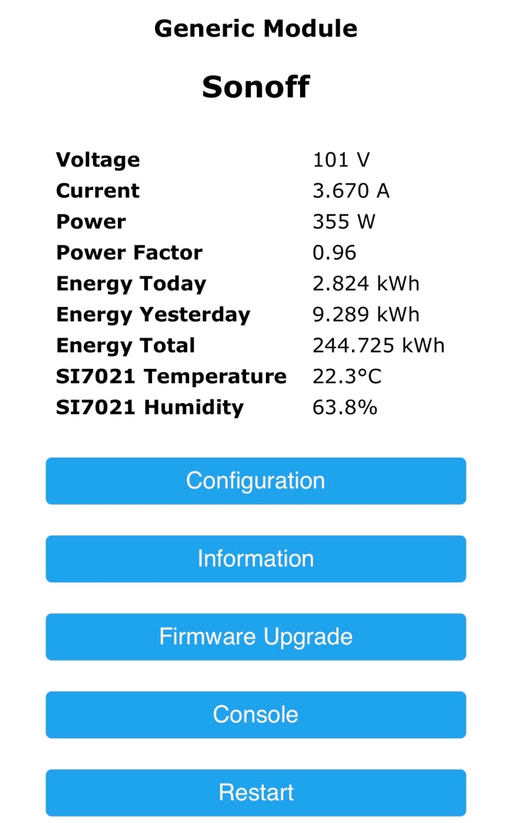
When switching on the power again, the PZEM and the USB powered NodeMCU should be working together and logging into the NodeMCU you should see the following. (WITHOUT THE TEMPERATURE INFO)
Next, how to extract the Tasmota’s PZEM004T information. Without any more steps the MQTT is receiving the following data.
To find this out I got lucky as this NodeMCU was a former BRUH Multisensor. Checking the logs and was able to find the JSON code to extract this information. I tested many ways to get the information from the PZEM MQTT messages. In the end after I got my results I stumbled on this page. https://github.com/arendst/Sonoff-Tasmota/issues/1595
UPDATE 2019.04.16: To simplify the process of the code below I have put it online at https://github.com/halfforked/PowerMeter/tree/master

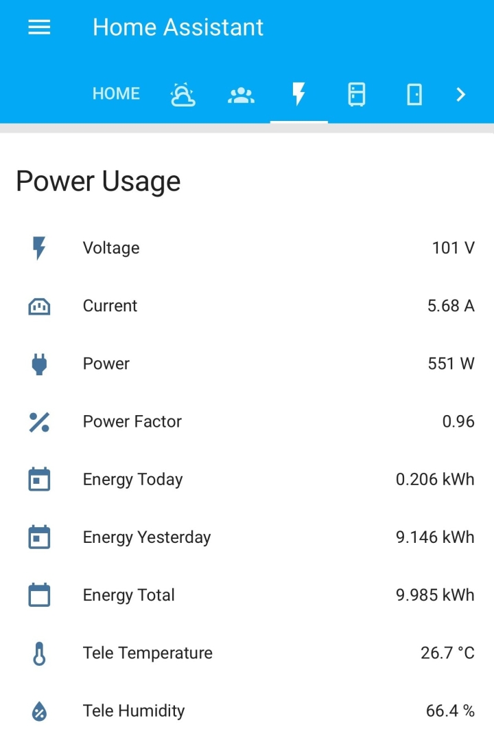
By entering the above as MQTT entities the data will be properly extracted to Home Assistant.
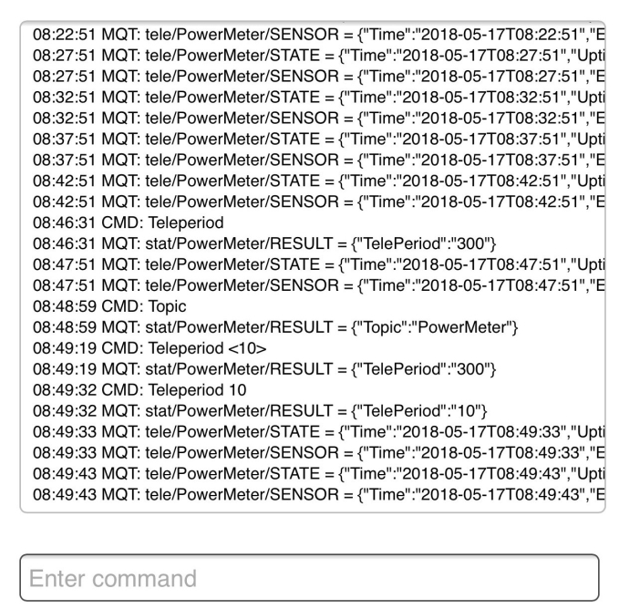
One problem I encountered was the slow update time of the information. The humidity and temperatures were updating by the second whereas the power updates were every 300 seconds.
[UPDATE 2019.09.11]
- OPTION 1 – On TASMOTA firmware v6.6.0 go to MENU – CONFIGURATION – CONFIGURE LOGGING – Telemetry Period and change the value to 10
- OPTION 2 – Changing the following TELEPERIOD setting is the original way. See below

Changing that to 10 seconds made everything so much better and usable. By entering “Teleperiod 10” to update every 10 seconds.
UPDATE 2019.05.05: If “Teleperiod 10” for 10 second interval updates is still too slow for your liking there is the possibility to update the Tasmota code as commenter SeByDocKy
Finally, I recompiled the last tasmota firmware and made the two following changes in the sonoff.ino (around line 1204)if ((payload >= 0) && (payload 0) && (Settings.tele_period < 10)) Settings.tele_period = 10; // Do not allow periods < 10 secondsWorks fine for Teleperiod 1
SeByDocKy‘s link: see the comments (I didn’t have time to test it myself, see comments for any issues that may arise)
This is an interesting workaround. However having said that I will be leaving the tasmota code untouched for the time being as 10 seconds doesn’t bother me so much. Plus I’m curious as to why there would be a 10 second minimum in tasmota in the first place. Long term usage to be the final test perhaps.
Congrats the safe part is done.
Just FYI this seems to be a good link to check for bugs with the PZEM. https://github.com/olehs/PZEM004T/issues

You could indicate how you calculate the Kwh and the power factor in Home Assistant with the Pzem. Thank you very much
LikeLiked by 1 person
@zacaruca the kWh and power factor (etc) were all part of the tasmota firmware presets.
I’ve edited the post to reflect that.
Thanks for the question.
LikeLike
Could you share home assistant configuration for display power monitor same you! Thanks so much!
LikeLiked by 1 person
Thanks for you request.
I’ve uploaded a screenshot of my settings in my configuration.yaml file for the power meter.
Please note I named it “powermeter” also the temperature and humidity are not needed unless you have that sensor.
LikeLike
I posted a link to a new github page where you can copy and paste the code I use.
https://github.com/halfforked/PowerMeter/tree/master
If you are looking to make the card that’s another issue. Do let me know if you need anything more
LikeLike
Does the PZEM004T need the 220V mains connection or can it also be powered only over the 5V from the TTL port?
LikeLiked by 1 person
From what I’m told
Update 2019.04.26 from Sendorm
One thing to add, I am powering the pzem-004t TTL from the nodemcu VU pin and it is working perfectly. It seems a separate usb power adapter is not necessary after all.
I think this is what you’re asking
LikeLike
Hi great project … I have to study it more but… in order to have the more compactness project, I guess it’s possible to replace the PZEM-004 with the PZEM-004T (w/o display) ? :
https://www.aliexpress.com/item/PEACEFAIR-PZEM-004T-AC-80-260V-100A-TTL-Port-Voltmeter-Electric-Kwh-Meter-Volt-Amp-Power/32966132995.html?spm=2114.search0604.3.28.64b250f7Sa7Yf6&ws_ab_test=searchweb0_0,searchweb201602_6_10065_10068_319_10891_317_10548_10696_10084_453_454_10083_10618_10304_10307_10820_10821_10301_537_536_10843_10059_10884_10887_321_322_10103,searchweb201603_16,ppcSwitch_0&algo_expid=531788b6-7ba3-41e9-93e6-31802fe12a11-3&algo_pvid=531788b6-7ba3-41e9-93e6-31802fe12a11
I guess also I can use a WeMos D1mini … and a dedicaced 220V to 5V power suply (>500mA should be ok for both ?)
LikeLiked by 1 person
Hi.
You could get the pzem-004 w/o display. I do mention that but personally I wanted to be able to test it before integrating it into hassio.
As for powering the unit.
I personally use a dual 100->5v USB adapter. Some people have reported success with powering the pzem via the 5v pin on the nodemcu/wemos d1mini
LikeLike
Thanks a lot … I will reproduce your project for my main electricy input but also for my electric water tank and my futur solar panel energy optimizer :). If you can extend a bit the grafana integration, can be great 🙂
LikeLiked by 1 person
Hi I received my PZEM-004T and I can confirm it can be directly powered via the “Vin” of a nodeMCU. Thanks to your blog, it took me 2min to have information in Home Assistant. Anyway, I am a bit frustrated by the 10s limitation of Telemetry information sent by Tasmota…. I would like to have about 1s…. Thinking to flash with ESPurna firmware instead which offer 1s and 6s options…
LikeLiked by 1 person
Awesome thanks for the update and confirmation.
If you do try another firmware please to let us know.
LikeLike
Finally, I recompiled the last tasmota firmware and made the two following changes in the sonoff.ino (around line 1204)
if ((payload >= 0) && (payload 0) && (Settings.tele_period < 10)) Settings.tele_period = 10; // Do not allow periods < 10 seconds
Works fine for Teleperiod 1
🙂
LikeLiked by 1 person
Wow. Fantastic that was fast. Do you mind if I update the blog entry with this info?
LikeLike
Of course 🙂
Here the .bin file modified for the NodeMCU (I got the banggood one)
https://mon-partage.fr/f/rBwt8Mfg/
LikeLiked by 1 person
Yes of course you can share this info.
Here is the modified .bin file for a nodeMCU (and I guess should work for a D1mino) : https://mon-partage.fr/f/rBwt8Mfg/
LikeLiked by 1 person
Updated! Thanks for the feedback and mods. As I mention in the post, I will not be attempting this as 10 seconds is tolerable for me, but it might be useful for others~!
LikeLike
I understand…. Personally, since I will install soon some solar panels, I will have three PZEM-004T+D1mini combo: one for the main electricity input, the second for my main electrical water tank and the third from the solar panel DC/AC converter. The Electrical water will be controled via a 4000W SCR. The idea is to send the maximum power to the water tank when the solar panel are producing. It’s cheaper to stock power in hot water rather than into battery. If course when the water tank will be hot enough, then power will be send to battery. So I need fast updated from these three devices to run the power distributor optimizer algorithm ran in home assistant
LikeLiked by 1 person
Hi,
I noticed something strange … with my system…. Now after 24h/30h of usage, my system “freezes” whatever the teleperiod value 😦 ….I have to reboot via the associated panel switch…
I don’t know if it’s from the PZEM-004T or my NodeMCU… Maybe linked with the fact that the PZEM-004T is directly powered via the NodeMCU….. I am investigating :(…
LikeLike
Ok it comes from my NodeMCU ….. It freezes after a couple of minute right now. Maybe when powering the PZEM-004T, he draws too much for NodeMCU circuit… then “freeze”….. Or maybe sensitive to the EMI around…. (My system is directly into my main electrical panel with a lot of AC wires around)
LikeLike
Ok …. After reading some stuff in internet…. some “freezing” are met with ESPcore > 2.3.0…. I recompiled tasmota with core 2.3.0. Seems more stable. Here is the new bin: https://mon-partage.fr/f/PVz3saWQ/
LikeLike
I had the same issue with 2.4.x
It was the first thought to my mind.
Can you give more details about the file?
Which tasmota version also which package?
LikeLike
It’s last tasmota version modified for Timeperiod >=1 s and linked with Core lib V2.3.0….. Unfortunatly it’s still freezing time to time 😦 …
I tried to play with the Dynamic Sleep option…. Still not perfect… 😦
If it’s not perfect…. I will go for espurna firmware instead
LikeLike
HI,
VERY IMPORTANT MSG….. I KILLED TWO PZEM-004T V2.0 (TTL) TRYING TO ADD A DHT22 SENSOR ON THE 3.3V, GND & D5 OF THE NODEMCU !!!!!!! SEEMS AS SOON THE DHT22 IS ALSO POWERED BY THE NODEMCU, IT KILLS THE CURRENT SENSOR OF THE PZEM-004T…. ONLY VOLTAGE WORKS AFTER…….. SO DON’T TRY TO ADD A DHT22 ON THE SAME NODEMCU OR USE ANOTHER POWER SOURCE!!!!! THE PROBLEM NOW ONLY PZEM-004T V3.0 ARE SOLD AND IT’S NO MORE TTL BUT MODBUS SO NOT YET TASMOTA COMPATIBLE
LikeLiked by 1 person
That is unfortunate. But thanks for the important PSA.
LikeLike
YEs 😦 …. I have no more sensor now 😦 ….
How you connected your DHT11 on the NodeMCU ? The DHT11 is working in 3.3V or 5V ? for you
LikeLike
My nodemcu powers a dht22 via the 3.3v pin.
It’s a reuse of a BRUH multisensor.
LikeLike
And your PZEM-004T is powered standalone ?
LikeLike
I use a double USB adapter. One USB port powers the PZEM-004T with provided cable. The other port provides power to the nodemcu via microUSB.
My DHT22 temp/hum sensor is powered from the nodemcu 3v3 pin.
LikeLike
THE PROBLEM NOW ONLY PZEM-004T V3.0 ARE SOLD AND IT’S NO MORE TTL BUT MODBUS SO NOT YET TASMOTA COMPATIBLE
I have PZEM004 V3. Does that mean these instructions do not work at all? I can’t get a reading on my NodeMCU…
Thanks for your help!
LikeLike
Marc, sorry to hear about your troubles.
As you have a v3 and I am unfamiliar with it. (I’ve only heard good things in that it’s possible to get real time information via other methods as opposed to every 10 seconds) there are some good posts about the modbus setup out there surely.
Home assistant forums are a good place to start.
As for a schematic, again as I’m unsure of the v3, I would rather not.
LikeLike
Maybe would be good idea that this only works for PZEMs V1 and 2, not V3 as all newly purchased PZEMs are V3…
LikeLike
So only the double USB powering….. is different from my setup…
Really I don’t understand what’s happened for my case… 😦
LikeLike
Ok I think I have the answer for my problem… In fact, PZEM-004T are not killed but my Wemos D1 mini instead.
Why ? Because, every pin of the 8266 should run @3.3V… and basically with the PZEM and the DHT2, the RX & TX pins received some fatal 5V.
So definitively, it’s strongly advise to modify the PZEM by adding a 1Kohms in order to transform the +5V TTL of the PZEM into a 3.3V. Then… use the 3V3 pin of the D1 mini to power the PZEM. In this situation, the DHT2 should run perfectly as well.
LikeLike
Previously in the comments there was a question about having to modify the pzem.
I did not modify and followed this.
“ALTERNATIVE: No modification required on the PZEM-004T. Rather than using the 3.3V output from the Wemos D1 Mini to power the PZEM-004T serial interface, use the same 5V buck converter output (also used to supply power to the display and the Wemos D1 Mini) as VDD on the PZEM-004T serial interface. This eliminates the need for the resistor and the need to modify the PZEM-004T in any way at all.”
LikeLike
Some updates… few days later…
got some good news and some bad one…
Good news: the system is reworking… with a new nodeMCU….
Bad news: the system freezes when the teleperiod is too low…
With 10s, it’s ok ….. for 5s it’s freezing….. Now testing 9s…. if ok for at least 24h, I will test 8s….
LikeLiked by 1 person
Good to know it’s up and running.
New nodemcu, did you modify the pzem or leave it untouched.
About your system freezing I’m not sure if the risk/benefit from going down from 10s to 9s or 8s is worth it.
LikeLike
Yes I modified the PZEM-004T with a 1Kohms resistant. Both the PZEM-004T & the DHT22 are powered via the two 3V3 pins of the nodeMCU.
Testing 9s… seems ok, at least no freeze after 12h… Will see tmr if the 24g test will be successful. If yes going down to 8s… and so on 🙂
LikeLiked by 1 person
8s worked for the 24h test … so now testing 7s 🙂
By the way, I think the future will be zap Tasmota for ESPhome….
It will be direct for Home assistant.
LikeLiked by 1 person
Great read thanks
Where you get the case.
was it supplied or 3d printed
cheers just ordered the parts
LikeLike
Hi Marty,
Thanks for the comment.
I assume you’re talking about the PZEM-004t case. I ordered the one with case, USB cable and, split coil. (The complete package)
LikeLike
Mate I seen them after I ordered a PCB only
Thanks
LikeLike
Hi, thanks so much for sharing this! However, I can’t get a reading on my nodeMCU. Would it be possible that you say something about how you connect the nodemcu with the PZEM? A picture, diagram or detailed instructions would really be helpful… For example, does the Nodemcu need to be plugged in to the microUSB? And if it is, do I still need to connect the VDD/GND of the PZEM? I’m not even sure if those connector need to be connected to a 5V power supply or if they deliver power… I find the serial connector of the PZEM very confusing and can’t find any clear answers online. Thanks in advance for any help!
LikeLike
https://github.com/arendst/Tasmota/wiki/PZEM004T-Energy-Monitor
The gpio settings look to be different for v3. I don’t know if this help of changes anything for you.
LikeLike
Thanks for your reply! I wasn’t aware that the PZEM has a GPIO. Only the port where you connect power and CT sensor and the TTL port which is the same as V1 and 2 (VDD, RX, TX, GND)
LikeLike
The connections on the PZEM I think are the same. But the settings in tasmota are different for the v3.
This is what I understood from the online forums.
LikeLike
Hi, greetings from Shizuoka 😉
Thank you for this guide.
Unfortunately I am struggling the same as Marc R does.
tried several settings for the GPIO without success to get any reading. Everything shows 0
I found this guide and I am starting to believe that the voltage on the serial pins is not sufficient to communicate?
https://tasmota.github.io/docs/PZEM-0XX/
This 1kohm resistor seems to raise the voltage on the TX pin? I am no electrician, to me this is all magic 😉
Did you really not have to modify anything? Can you maybe measure what voltage you have on your RX/TX pins? maybe something is different.
I will probably try the 1kohm thing next, in the hope nothing blows up 🙂
Best Regards
LikeLike
Hi Sebastian,
I did no modifications. The connections are straight. I did change the nodemcu at one point as I ungraded Tasmota, that was a straight transplant.
The new pzem has some quirks. I’m sure you’ve read the comments to get this far.
Adding a resistor is generally a safe thing to do.
There may be a difference in voltages, I wouldn’t hold your breath but if I remember to do it I’ll check the voltages.
Please Do let me know if you have any success.
LikeLike
So in the end I ended up buying a new PZEM and now I got everything working. Not with the NodeMCU but a Sonoff basic. Without resistor mod.
Apparently I managed to break the first PZEM in the process. Probably I applied 5v after I did the resistor mod.
Also I should have had a look at my breaker box before doing all this. Turns out I have a 3 phase breaker…
I am working around it by only measuring 100V phase at the breaker with the PZEM and measuring the 200V aircon separately. (Adding it up as total power consumption in HA)
Seems to work so far.
LikeLiked by 1 person
Thanks for letting us know how it went!
LikeLike